
Once you have placed your frames, accessories, and custom parts, you can use the update button to have Inventor calculate the connectors for your project.
This process is automated and will take basic rules into account to correctly connect frames depending on which type of connection is required.
The Update tool has the exact same backbone and rules as the one available on the beCAD online platform.
As with every automated process, it’s very important to always review the connections and make changes where it’s needed. In some cases, new parts and frames are not yet included in the calculation and therefore will also not be correctly included in the process. The tool is constantly being updated to include these connections as soon as possible.
Please note that custom parts made from scratch will never be included since the possibilities are endless, and take thorough review to include all the required connections.
Custom-made parts based on standard parts will be included in the process based on their standard counterparts.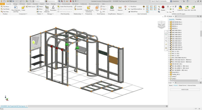
The main rules for connectors are as follows:
-
At each straight connection, 2 double clamps and a 180° PIN without bolts on the bottom
-
At each L-connection, 2x 90° PINS at the top and bottom with M8 bolts on all sides
-
At each T-connection, 2x T6 PINS at the top and bottom with M8 bolts on all sides
-
All horizontal covers are fixed with the M8 + COVER SLIDER. Vertical covers are placed with the green cover clips
-
Every 3 meters there has to be either a return frame or baseplate, depending on the height of the wall. Additional ballast may be required.